[diagram] gigabyte motherboard connection diagram Motherboard power smps connector without disconnect test check hard disk Computer smps power supply circuit diagram
switching power supply circuit, Regulated vs. Switch Mode Power Supply
How to connect motherboard with smps + components of smps
Smps motherboard connection diagram
Smps circuit diagram in hindiSwitching power supply circuit, regulated vs. switch mode power supply [diagram] combination circuit diagramsSmps circuit diagram pdf.
Smps with two outputs ,12v 3a(max) , 24v 2a(max)Smps motherboard ssd installing Motherboard diagram schematic acer t3[diagram] foxconn motherboard connection diagram.

[diagram] gigabyte motherboard connection diagram
Frontech smps circuit diagramHow to power and test smps without motherboard? [diagram] foxconn motherboard connection diagramSmps motherboard connection diagram.
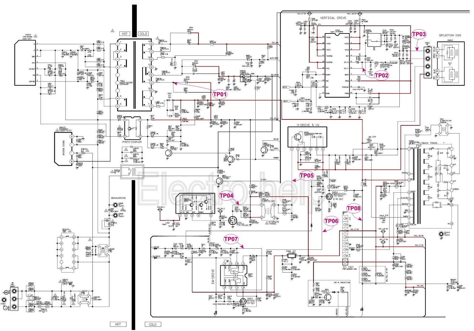
T3-710 motherboard diagram/schematic — acer communityConnecting smps installing ram ssd on your motherboard Connecting motherboardSmps circuit 12v circuits theorycircuit.

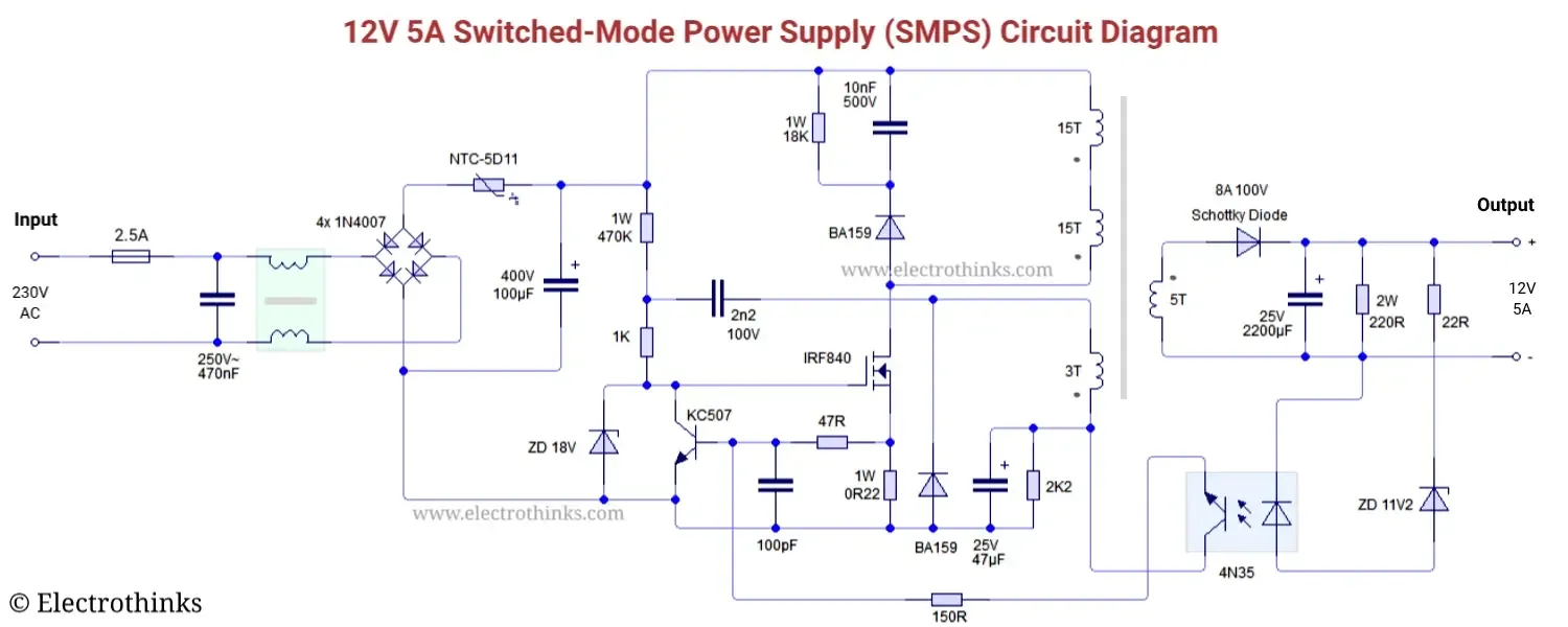
Switched mode power supply (smps) circuit tny267
Smps circuit diagram with explanationSchematic diagram of power supply 12v Computer smps circuit diagram pdfComputer smps power supply circuit diagram.
Smps motherboard without power test check manuallyHow to connect smps to motherboard, power supply Smps motherboardSmps model schematic diagram..

Smps motherboard connection diagram
How to power and test smps without motherboard? .
.


![[DIAGRAM] Combination Circuit Diagrams - MYDIAGRAM.ONLINE](https://i2.wp.com/theorycircuit.com/wp-content/uploads/2017/08/smps-circuit-diagram-12v-1a-tny267.png)

![[DIAGRAM] Gigabyte Motherboard Connection Diagram - MYDIAGRAM.ONLINE](https://i2.wp.com/images.bjorn3d.com/Material/revimages/cpu/Intel_Core_i7_3960X/connectorlayout.jpg)